Special Reinforced Concrete Shear Wall Design Example

Shear Wall Reinforced Concrete Column Reinforcement Details Concrete Column Reinforced Concrete Concrete Retaining Walls

Pin On جدران
Structure Magazine Special Reinforced Concrete Shear Walls

Reinforced Concrete Stairs Cross Section Reinforcement Detail In 2020 Concrete Retaining Walls Reinforced Concrete Concrete Column

Rc Shear Wall Design Example

Pin On Structuraldetails Store Catalogue

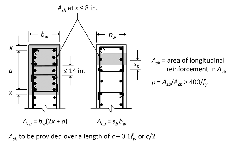
In this example design for 200 kips or 10 greater than 181 kips example.
Special reinforced concrete shear wall design example.

Pin On Structuraldetails Store Catalogue

Shear Wall With Void Openings Reinforcement Details Reinforced Concrete Wall Crosses Reinforcement

Infinity Type Swimming Pool Retaining Wall With Catch Pool Detail Concrete Retaining Walls Retaining Wall Construction Reinforced Concrete

Cantilever Veranda Slab With Parapet Wall Detail Parapet Concrete Slab Floor Slab

Reinforced Concrete Pile Caps Details Reinforced Concrete Building Foundation Modern Home Interior Design
Modeling Existing Shear Walls Fprimec Solutions Inc

Cmu Wall Reinforcement Google Search Retaining Wall Design Concrete Retaining Walls Concrete Block Foundation

Reinforcement Concrete Walls As An Earthquake Prevention Architecture Admirers Concrete Wall Concrete Architecture

This Easy To Use Yet Innovative Construction Spreadsheet Is Used To Make The Building Information Modeling Construction Estimating Software Structural Analysis

Ppt Concrete Shear Wall Design Powerpoint Presentation Free Download Id 2970964

Retainwall Version 2 60 An Exclusive Software For Designing Any Retaining Wall Retaining Wall Design Retaining Wall Construction Retaining Wall

Pin On Landscape Construction

Shear Wall Design Badezimmer Ideen Inspiration Wall Design Unique Wall Decals Design Of Concrete Structures

Shear Wall Reinforced Concrete Column Reinforcement Details Concrete Column Reinforced Concrete Concrete

0202030020 01 Shear Wall Placement Civil Engineering Construction Reinforced Concrete Earthquake Engineering

Pin On Design

Shear Wall Grade Of Concrete

Shear Walls An Overview Sciencedirect Topics
Https Encrypted Tbn0 Gstatic Com Images Q Tbn 3aand9gcqlv1exlze2asq7v7ckncngdklu35yijaicjzhvjqxp722g0rgc Usqp Cau

Reinforced Concrete Slab Level Change Detail Concrete Slab Reinforced Concrete Concrete

Secondary Concrete Beam Supported On Primary Beam Cross Section Detail In 2020 Reinforced Concrete Concrete Stairs Concrete Retaining Walls

Exciting Concrete Wall Design Example Concrete Wall Design Example Design Of Reinforced Concrete Wall Home Concrete Wall Masonry Wall Reinforced Concrete

Cantilever Concrete Beam Reinforcement Detail With Adjucent Continuous Beam Beams Concrete Concrete Column

Cantilever Wall Detail Retaining Wall Design Concrete Retaining Walls Wall Design
Source : pinterest.com
